Home > Services > Speciman Adaptation
Speciman Adaptation
For the investigation of vehicle brakes on the flywheel dynamometer, an adaptation of the real vehicle components to the mountings of the flywheel dyno is required. The task of the adaptation is to fix the vehicle components securely in the test stand and, in addition, to maintain the degrees of freedom present in the vehicle.
For pure function tests on a wheel brake, steering knuckle adaptations are used, which we manufacture according to your wishes, e.g. on a round flange in welded design.
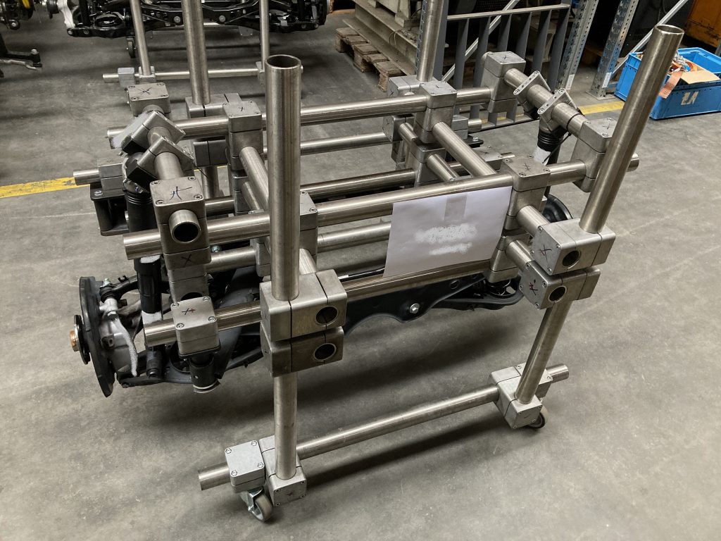
Suspension strut and complete axle assembly adaptations are used for examinations including chassis parts. Our solution is based on the proven tubular system in truss or frame construction. Stainless steel tubes are connected very rigidly to each other by means of aluminium clamps. The superstructures are specially adapted to your test specimen and are almost 100% recyclable even after many years of use. The actual contact between the tubular frame manufactured by us and the vehicle axle components supplied by you is made by specially manufactured turned and milled parts which are welded onto back plates for connection to clamping blocks and thus reproduce the bearing points in the vehicle. The picture shows an example of such a structure.
NVH (Noise-Vibration-Harshness) investigations in particular place high demands on the precision and rigidity of the adaptation frames. With our many years of experience, we offer you three different adaptation methods that differ in terms of the achievable accuracy:
1.) Standard Adaptation (without specifying coordinates)
In standard adaptation, the vehicle axle or wheel suspension is adapted in the tube frame without any knowledge of the spatial position in the real vehicle, as well as without knowledge of the wheel suspension components among each other. The essential requirements are that the axle components are securely fixed in the adaptation frame, that the degrees of freedom available in the vehicle are maintained and that the wheel centre axle is at the height of the test bench drive shaft in the deflected (relaxed) state.
Advantages of this method:
- No confidential data required
- Low effort
- Low costs
Disadvantages of this method:
- No consideration of the vehicle geometry data
- No consideration of vehicle kinematics
- Wheel lift curve not like in real vehicle
- No transferability between two bodies
- High variances between bodies
2.) Adaptation according to coordinate point method (KOOPV)
With the “coordinate point method (KOOPV)” it is possible to position a vehicle axle (or the wheel suspension) similar to the vehicle in the tubular frame. In this process, the position and spatial location of the vehicle axle and the suspension components are determined during production using a special procedure. This allows the real position in the vehicle to be reproduced with an accuracy of approx. ± 4 mm. The geometric parameters of the wheel suspension as well as the wheel lift curve are consistent with the real vehicle within these limits and can be manufactured in a correspondingly reproducible manner. Thus, comparable measurements and a validation of several identical axle adaptations among each other are possible.
The Z-position of the vehicle axle in the tube frame represents a 100% wheel load position, so that the required real wheel load occurs when the wheel centre plane and test stand shaft centre are aligned. For this purpose, the wheel carrier is lifted from its deflected position until it is aligned with the test stand shaft, while the tubular frame remains connected to the test stand floor.
The position of the specified connection points is checked continuously during production and finally by subsequent measurements before delivery.
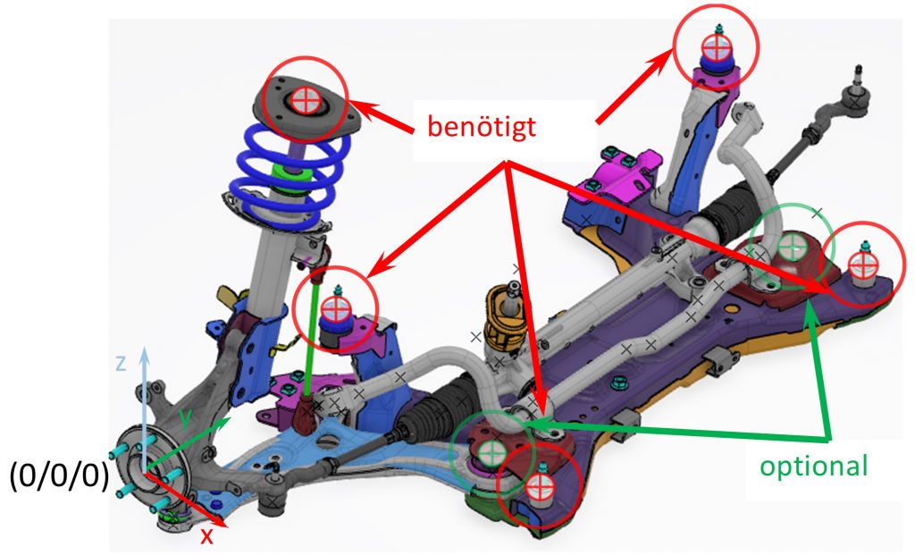
For this method, the coordinates of the connection points must be known, see picture.
Advantages of this method:
- No CAD data required, only coordinates
- Reasonable effort / costs
- Vehicle geometry largely corresponds to real vehicle (approx. ± 4 mm)
- Vehicle kinematics largely corresponds to real vehicle
- Wheel lift curve comparable with real vehicle
- Wheel load tests possible
- Wheel load tests representative
- Very low variance of geometric axle parameters
- Reproducible production / manufacturing
- Comparable measurement results
- Reproducible measurement results
Disadvantages of this method:
- Information of the connection points (coordinates) needed, information procurement difficult due to data protection and confidentiality agreements
- Engineering input needed
3.) High-precision adaptation using 3D printing processes
The high-precision 3D printing adaptation process was developed by TRM in collaboration with a cooperation partner. To realise a high-precision alignment of the axle parts in the adaptation frame, the bearing connection points are first isolated from the CAD model of the axle and defined, orthogonal connection surfaces are created. The components developed in this way are realised using 3D printing technology and brought exactly into position with a profile frame on the assembly table (see picture). The tubular frame is “built” around the now existing connection points of the axis. After completion and quality inspection, the 3D printed parts are removed and replaced by the real, pre-stressed axle.
High-precision aligned 3D printed part enables precise connection of the welded construction
This method requires a lot of experience to implement and is more complex than the two methods described above. However, experience has shown that it provides very good results and the best possible positioning of the vehicle axle on the test bench. It is particularly suitable for investigating complex vibration phenomena on the test bench in the entire frequency range.
Advantages of this method:
- Enables investigation of complex vibration phenomena in the entire frequency range
- Vehicle geometry corresponds to the real vehicle as closely as possible according to the state of the art (approx. ± 2 mm)
- Vehicle kinematics correspond to the real vehicle as far as possible
- Wheel lift curve comparable with real vehicle
- Wheel load tests possible
- Wheel load tests representative
- Very low variance of geometric axle parameters
- Reproducible production / manufacturing
- Comparable measurement results
- Reproducible measurement results
Disadvantages of this method:
- 3D CAD data required, information difficult to obtain due to data protection and confidentiality agreements.
- Increased costs, engineering input, time and material